Creating a Drawing Frame in Autocad
 In AutoCAD tutorial series I've posted, we have created our reusable contents, and use it to draw a building plan. Now, we are going to create some schedules from it. We are going to create a door schedule, column schedule, and a wall schedule. It's not just Revit that can do that!
If you have created your own floor plan, you can use it. Or simply download this one for this tutorial.
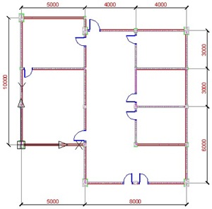
Open your file (or mine). My file will look like this. You should be familiar with these objects :)

Door Schedule
We can create a schedule using data extraction. It's on your ribbon bar> insert> linking & extraction> extract data.

This will open data extraction wizard. I've posted about this before, to create a report of lines length and coordinate, so I won't be write many details this time.
Page 1 – Begin
This is the first time we use data extraction, so use create a new data extraction. Click next, and when AutoCAD ask you for file name, give it door schedule.dxe. You can use this file again later when you need to create another door schedule. Save it.
Page 2 – Define Data Source
AutoCAD give you a choice: you want to create a data extraction from file(s) or from some objects in your drawing. If you have several floor plans in one drawing, you can select them separately. But now let's just use drawing/sheetset. Click next.
Page 3 – Select Objects
AutoCAD will recognize all type of objects you have in your drawing. Now we need to filter what kind of objects to be included in the schedule. Let's just select the SingleDoor, and left the rest unchecked. Click next.
Page 4 – Select Properties
This time we will need to define which properties we want to be included in our report. We only need the door width. Let's filter it first.
On the right column, category filter, uncheck everything except Dynamic Block. Now it should be only 3 properties left. Check only Width.

Where's this width property come from? We define it by renaming the parameter to width. You can find more details in this dynamic block tutorial.
Page 5 – Refine Data
In this page you will see your schedule preview. Nothing hard here. You can sort your data by clicking the header name. Or you can arrange the column by dragging the header name. You can also choose several other options here. Try them, you can see the preview right away. Click next after you've done.

Page 6 – Choose Output
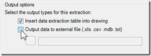
On the next page, we can select where we want to put this schedule. You can put it in your drawing, or save it to external file (excel, database, or text).

Click next.
Page 7 – Table Style
If you use your own drawing, you might not yet set your table style. If you use mine, just use the standard table style. Type the table title 'Door Schedule'. Click next.
Page 8 – FInish
Nothing here :) It's just telling you you're done. Click finish. Now place your table to your drawing. Or if you choose external file, then you're done.
Column and Wall Schedule
So what about column and wall schedule? Sure, you can create them too. You should try it by yourself.
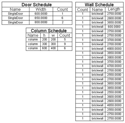
Pay attention to door and column schedule. Remember we only have one door block and one column block. But in this schedule, we can see 3 door type and 3 column type! Yup, their size are different. Data extraction can recognize it. It's great isn't it?

Unfortunately for wall schedule, we can't sum them all and only list wall with the same name. It will only group wall with the same length and name. If you want to do more than that, you should choose the output to external file. Edit it in excel, then import it back. But at least you don't have to count them manually ;)
You can also use data extraction to report any kind of data your drawing have. Points coordinate, line length, everything! I wrote how to report line length, coordinate, layer, and color here. Some one ask me that question to create laser cutting estimation.
Source: https://www.cad-notes.com/creating-schedule-from-your-autocad-drawing/
0 Response to "Creating a Drawing Frame in Autocad"
Post a Comment